
Introducing Bluetooth Azimuth Elevation Rotator
BTRotator
In November 2023, I made a DXpedition to Cocos Island in the Indian Ocean. At that time, I needed an antenna rotator to track the communications satellite IO-117 RS-44. However, there were no small and lightweight commercially available products, so I made one myself. It worked Fine. I showed this sample unit at Japanese Ham fair 2023 August.Several people have asked if I could sell it. I posted on X and received messages from many people who is interest in.
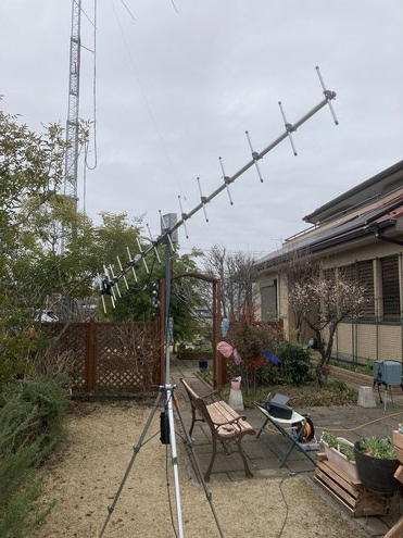
The photo on the left shows an example of a 430MHz 15-element Yagi antenna attached to access the IO-117. The antenna is controlled via Bluetooth connection, so the antenna and transceiver can be connected with just one coaxial cable. I use an IC-9700 transceiver and a PC running satellite tracking software called SatPC32, which automatically adjusts the Doppler frequency. The antenna is automatically tracked, so QSOs can be made by simply clicking on the PC screen.
Satellite Tracking System
The satellite tracking and QSO equipment using this unit is as shown in the diagram below.

The diagram above shows the configuration when using this unit to track satellites while conducting QSOs using a transceiver. The equipment on the far left is the unit mounted on a tripod.
This unit operates on a low power 12V power supply, so it can be easily used with any battery that has a 12V output, such as a smartphone charger.
The PC runs automatic tracking software. The software that is currently confirmed to work is SatPC32, which has many users worldwide.Satellite tracking is performed using this software.
Your PC must have Bluetooth capability. This Bluetooth function is used to communicate with the unit and control the azimuth and elevation angles.
The transceiver and antenna are connected by a coaxial cable. Normally, two cables,Normally, two cables, one for 144MHz and one for 430MHz, are used, but by using a Duplexer,it is possible to operate with just one cable.
Explanation of unit.
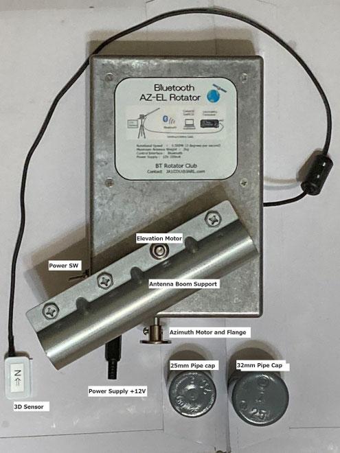
A) 3D sensor
It contains a board equipped with a sensor chip for measuring azimuth and elevation angles.
Attach this part to the antenna boom. To install, make sure the label with the arrow is on the top.
The control program inside the controller controls each motor so that when the power is turned on, the arrow points north and the antenna points horizontally.
The cable length is approximately 50cm. Please install it as far away from the antenna radiator as possible and also from the main unit.
B)12V Power Supply
This is the 12V power supply terminal for operating this unit. 12V is supplied to the motor. 5V and 3.3V are also generated internally from this 12V power supply to power the CPU. Since 12V is mainly supplied to the motor, a wide range of voltages from 8V to 14V is fine if you don't care too much about the motor rotation speed. The connector is a standard DC jack, with the center being positive (+).
C) Azimuth/Elevation Rotor Axis
This machine has two rotation axes: one for azimuth rotation, with a half-moon shaft of 6.0 mm diameter. Fix the accessory flange with a 6mm diameter socket, insert this shaft and secure the rotator. The elevation rotor shaft has a 6mm diameter bolt shaft. Attach the antenna boom to the antenna boom mounting bracket and tighten the bolt with a nut. The elevation rotor shaft has a 6mm diameter bolt shaft. Attach the antenna boom to the antenna boom mounting bracket and tighten the bolt with a nut. The torque of the rotation axis is 25kg cm, so it is not large. When installing the antenna, please install it at the boom's center of gravity so that the rotation torque is as small as possible. If you cannot attach it at the center of gravity properly, attach a counterweight to the lighter side to balance it.
D) Power Switch and LED
The power switch and LED are located at the bottom left of the front of the unit. The LED will light up when 12V is turned on. When the power is turned on, the built-in CPU starts working and, while watching the signal coming from the 3D sensor, it operates so that the elevation angle is 0 degrees (horizontal) and the azimuth angle is 0 degrees (north), and when it reaches the designated position, it turns in that direction and stops. At this time, please make sure that the antenna cable and power cable are not wrapped around the support pole. When installing, it is better to leave the antenna cable unattached, turn on the power and point it to the north, then attach the coaxial cable to prevent the cables from becoming tangled.
Inside of BT Rotator
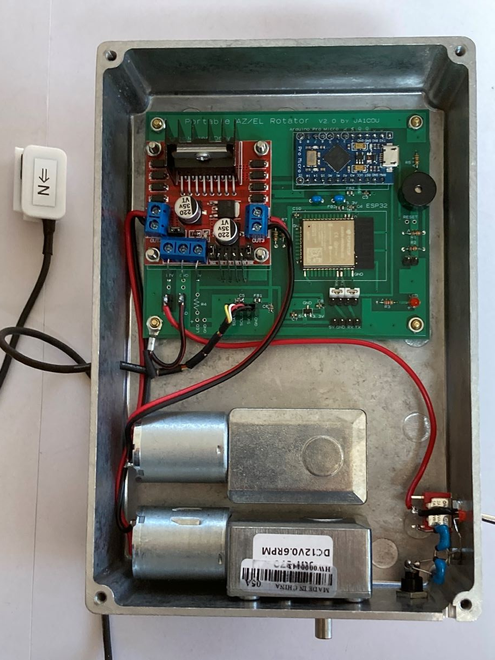
This unit consists of a printed circuit board
containing all the electronic circuits, and two
motors which determine the azimuth and
elevation angles.
The external connection is made via two
lines. a 3D sensor and a 12V power supply.
The case is made of die-cast aluminum, and if the lid is closed completely, the radio waves to the Bluetooth chip will be blocked.
Therefore, there are holes under the labels on the front and back of the device to allow the Bluetooth signal to pass through. The Bluetooth signal communicates through these holes.

Go to Shop Page
Contact : JA1COU@jarl.com
BT Rotator Club
E-mail: ja1cou@jarl.com